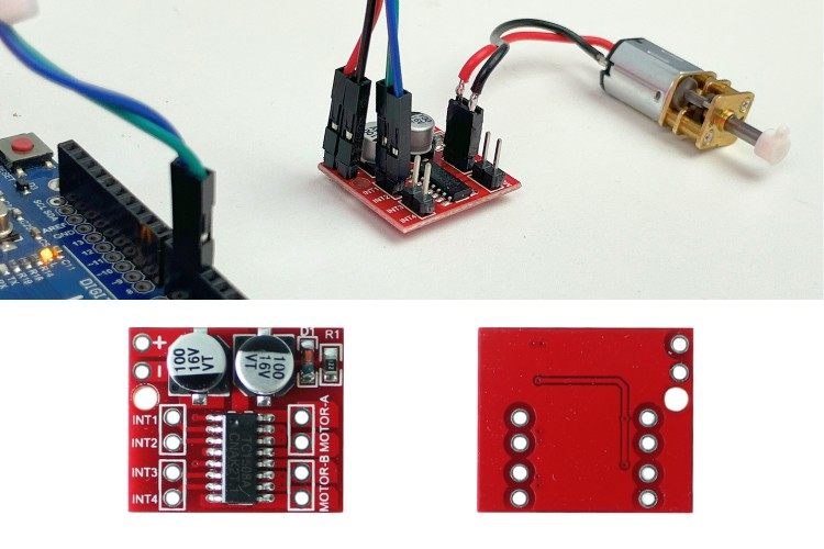
Today we are going to learn about one of the affordable DC Motor Driver modules that is used to drive small low-power motors like N20 and N10 DC motors. One of the popular choices for DC motor control is the L293D motor driver IC, but today we have better options that are more efficient and can drive higher current with in-built protection features. We have built a lot of projects with motor drivers previously, you can also check them out if your are interested.
Now, without further ado, let's move on to today's topic of interfacing the MX1508 DC Motor Driver with Arduino.
MX1508 Motor Driver
The MX1508 is a dual-channel DC Motor Driver with a built-in power MOSFET full-bridge drive. It is ideal for use in battery-powered smart cars, toy cars, and robots.
Fake MX1508 Motor Drivers: Ideally the main IC in this module should be MX1508. But, turns out this IC has some equivalents, so sometimes you may be shipped with modules which have different IC names on them. One of the equivalents we are working on today is the TC1508. The only thing to keep in mind is that you need to verify the appropriate datasheet with the requirements and specifications of your project. Most equivalent IC's will work exactly same, so you don't have to worry much about this.
Now lets check out the features of MX1508 Motor Driver Module:
Equipped with dual-channel built-in MOS bridge driver.
It can drive forward and reverse and also has stop and brake functions.
Ultra-low standby current and operating temperature.
Low ON resistance (1.6 ohm) in MOSFETs.
Maximum continuous current up to 1.8A per channel, with a peak of up to 2.5A.
Wide operating voltage (2.4 - 7.2 V).
Hope you got some idea about this module. Now let’s learn some in-depth specifications of the module.
MX1508 Motor Driver Module Specifications
As I said before, there are some clones and equivalents for this module that have different ICs. The module we have consists of the TC1508 integrated circuit. So, the specifications we will be covering will entirely depend on the TC1508 IC. Consider this before looking at the following data. Check the IC in your module, search for its datasheet, and learn about it before using it.
| Parameter | Symbol | Limits | Limits | Limits | Unit |
| Min | Typical | Max | |||
| Supply Voltage | Vcc | 2.4 | 5 | 7.2 | V |
| Motor Operating Current-Peak / channel | Iop−peak | - | - | 2.5 | A |
| Motor Operating Current-Continuous / channel | Iop-cont | - | 1.8 | - | A |
| Control Circuit Operating Current | Ictrl | - | 0.3 | 1 | mA |
| Circuit Shutdown Current | Isd | - | 0 | 10 | µA |
| High-Level Input Voltage | Vih | 2 | - | - | V |
| Low-Level Input Voltage | Vil | - | - | 0.8 | V |
| High-Level Input Current | Iih | - | 5 | 20 | µA |
| Low-Level Input Current | Iil | -1 | 0 | - | µA |
| Output ON Resistance | Ron | - | 1 | 1.6 | Ω |
| Operating Temperature | Top | -25 | - | 85 | °C |
| Storage Temperature | Tstg | -55 | - | 150 | °C |
Above you can see the detailed specifications of the driver module that has the TC1508 IC in it. In case you have a module with the MX1508 IC, below are some unlike specs:
Operating voltage range: 2V to 9.6V
Motor peak current: 2A (rear wheel), 1.5A (steering wheel)
Motor continuous current: 0.8A (steering wheel)
Next, we are going to meet the actual hardware!
MX1508 Pinout
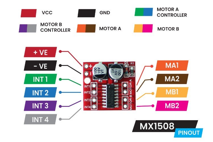
As shown the pinouts of MX1508 motor driver module are straightforward. It is similar to most motor driver modules, but the only difference is that it has no separate voltage input for the motor and logic circuit.
Above, you can see the pinout diagram of the MX1508 DC Motor Driver Module. This module is more compact, but according to me, one of the downsides of this module is that it is not breadboard friendly. You either need to solder wires directly onto the PCB or solder berg strips individually and use jumper wires to interface with it.
So, next, we will look at our hand-prepared pin description table for a clear understanding of the pinouts.
| Pin No | Pin Name | Type | Description |
| 1 | +VE | Power | Positive Power Supply (2.4 - 7.6v) |
| 2 | -VE | Power | Ground Connection |
| 3 | INT 1 | Digital Input [PWM] | Control Pins for Motor A |
| 4 | INT 2 | Digital Input [PWM] | Control Pins for Motor A |
| 5 | INT3 | Digital Input [PWM] | Control Pins for Motor B |
| 6 | INT4 | Digital Input [PWM] | Control Pins for Motor B |
| 7 | MB2 | Digital Output [PWM] | Motor B Output |
| 8 | MB1 | Digital Output [PWM] | Motor B Output |
| 9 | MA2 | Digital Output [PWM] | Motor A Output |
| 10 | MA1 | Digital Output [PWM] | Motor A Output |
Here, the +Ve and -Ve are used to supply power to the module. INT1 and INT2 pins are used to control Motor A connected to MA1 and MA2. Similarly, INT3 and INT4 pins are used to control Motor B connected to MB1 and MB2 pins. Like other drivers, it has an H-bridge inside which can be utilized to drive the motor either forward or backward, even at variable speeds using PWM.
Next, let us look at the in-depth review of the hardware.
MX1508 Motor Driver Module Working
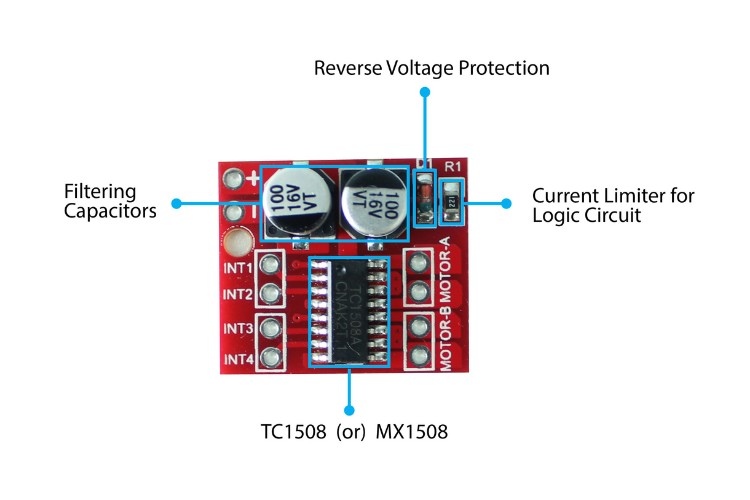
Below, you can see the overall component-wise information of the MX1508 module. The main component that consumes space on the module is the capacitor used for filtering the voltage rails and smoothing them. The other three components are very small.
I mentioned TC1508 or MX1508 near the IC because there is a possibility of receiving either of these or some other IC. In the above image, you can see that I received the TC1508 IC. Be aware of this when dealing with your module.
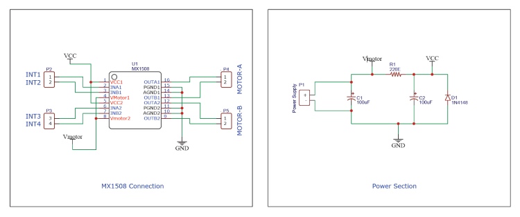
As there are not many components, the schematic is easy to understand. Below is the schematic of the MX1508 Module.
The schematic can be divided into two main sections: the Power Section and the MX1508 Connection Section. In the Power Section, there are two large electrolytic capacitors used to filter noise from the input voltage. The motor voltage supply pin of the IC is directly connected to the input voltage, with a 220-ohm resistor placed between the control logic circuit and the input voltage to limit current flow to the control logic circuit. A diode is also included for reverse voltage protection.
In the MX1508 Connection Section, all necessary pins are easily accessible for connection.
One important addition recommended is to add a 100nF capacitor in parallel to both motor output pins, which is not done by default in this module. This addition helps in noise suppression, filtering high-frequency noise, stabilizing the power supply, and improving overall performance.
Next, let's look at how we can use this module in our projects.
How To Use MAX1508 Motor Driver Module
This module can generally be used in two ways: standalone and with microcontrollers. In either way, the operating logic is the same and simple.
Each motor has separate dedicated two input pins to control its rotation. For precise reference, please refer to the chart below for a clear understanding.
| INPUT | OUTPUT | Function | |||
| IN1 | IN2 | IN3 | IN4 | ||
| LOW | LOW | - | - | Motor A | Standby |
| HIGH* | LOW | - | - | Motor A | Forward |
| LOW | HIGH* | - | - | Motor A | Backward |
| HIGH | HIGH | - | - | Motor A | Break |
| - | - | LOW | LOW | Motor B | Standby |
| - | - | HIGH* | LOW | Motor B | Forward |
| - | - | LOW | HIGH* | Motor B | Backward |
| - | - | HIGH | HIGH | Motor B | Break |
| *Instead of HIGH, providing a PWM signal will provide control over the speed of the motor. | |||||
IN1 & IN2 control Motor A, while IN3 & IN4 control Motor B. The MX1508 includes built-in pull-down resistors on all inputs, so if left unconnected, the pins default to a LOW state.
When both inputs are LOW, the module is in standby mode, effectively turned off. When both inputs are HIGH, the module enters brake mode, holding the motors in place like a braking system. When one input is HIGH and the other is LOW, the motor rotates in a specific direction. Notably, if the HIGH input is a PWM signal, it adjusts the motor's speed accordingly.
Knowing this you can use this module wisely. So next let's interface this module with Arduino UNO.
Components Required for Interfacing MX1508 Motor Driver Module with Arduino
Below is the list of components required for interfacing the MX1508 DC Motor Driver Module with Arduino.
Arduino UNO R3 x1
MX1508 Module x1
N20 Gear Motor x1
Connecting Wires - Required Quantity
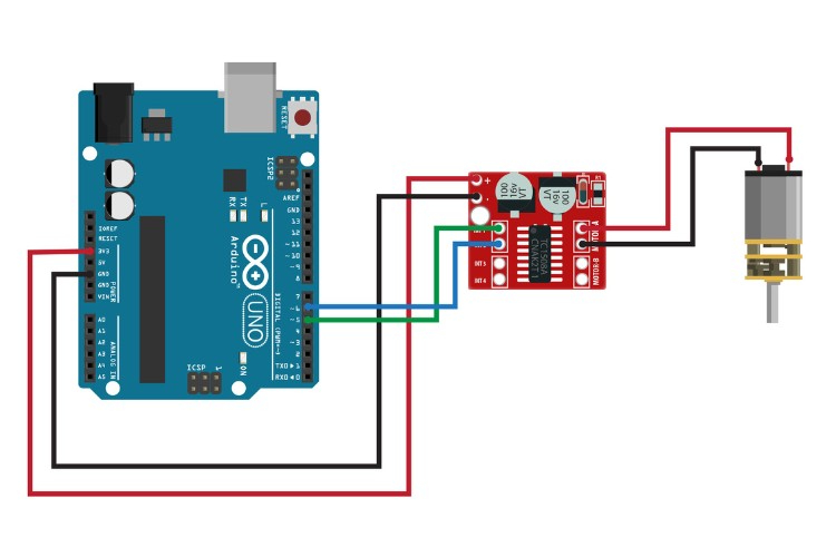
Circuit Diagram for Interfacing MX1508 Motor Driver Module with Arduino
For demonstration purposes, I'm using a single N20-type gear motor. Its operating voltage is as low as 2.5V, which makes it perfectly suited for this driver module.
Above, you can see the circuit diagram illustrating the interfacing of the MX1508 DC Motor Driver Module with an Arduino. Let's discuss the wiring of the circuit.
The MX1508 module is powered using 3.3V.
Since we need to adjust the speed of the motor, we should use digital pins that support PWM. Therefore, I'm choosing pins 5 and 6 of the Arduino UNO and connecting them to IN1 and IN2 of the Motor Driver Module.
As we're focusing on controlling Motor A, the N20 motor is connected to the MA1 and MA2 pins of the Motor Driver Module.
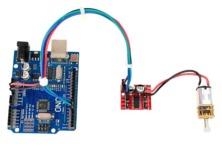
Above, you can see the assembled image of the components. With the connections completed, let's move on to coding the Arduino board.
Coding for interfacing MX1508 Motor Driver Module with Arduino
The goal of this project is to rotate the motor shaft back and forth at a fixed speed using an MX1508 Motor Driver Module and an Arduino.
First, we declare the necessary variables and define the pin connections:
// Define pin connections and settings
const int ForwardPin = 6;   // Pin for forward motor control
const int BackwardPin = 5;  // Pin for backward motor control
const long ActionTime = 200; // Duration for motor action (milliseconds)
const int MaxSpeed = 110;    // Maximum speed (0-255)
bool DirectionFlag = true;   // Direction flag for motor control
ForwardPin is connected to pin 6 for forward motion.
BackwardPin is connected to pin 5 for backward motion.
ActionTime is the time delay between direction changes (200 milliseconds).
MaxSpeed sets the motor speed (range 0-255).
DirectionFlag helps alternate the motor's direction.
In the setup() function, we initialize the motor control pins as outputs:
void setup() {
  // Set motor control pins as outputs
  pinMode(ForwardPin, OUTPUT);
  pinMode(BackwardPin, OUTPUT);
}
ForwardPin & BackwardPin is configured as Digital Output Pins. This configuration is necessary to control the motor's direction and speed.
Loop
The loop() function contains the main logic for controlling the motor's direction and speed:
void loop() {
  if (DirectionFlag) {
    // Drive motor forward
    analogWrite(ForwardPin, MaxSpeed);  // Set forward motor pin to MaxSpeed
    delay(ActionTime);                  // Wait for ActionTime
    analogWrite(ForwardPin, 0);         // Stop motor
    DirectionFlag = !DirectionFlag;     // Toggle direction flag
    delay(20);                          // Short delay before changing direction
  } else {
    // Drive motor backward
    analogWrite(BackwardPin, MaxSpeed); // Set backward motor pin to MaxSpeed
    delay(ActionTime);                  // Wait for ActionTime
    analogWrite(BackwardPin, 0);        // Stop motor
    DirectionFlag = !DirectionFlag;     // Toggle direction flag
    delay(20);                          // Short delay before changing direction
  }
}
Forward Motion: When DirectionFlag is true, the motor runs forward at MaxSpeed for ActionTime milliseconds, then stops. The flag is toggled to false, and there's a short delay before changing direction.
Backward Motion: When DirectionFlag is false, the motor runs backward at MaxSpeed for ActionTime milliseconds, then stops. The flag is toggled to true, and there's a short delay before changing direction.
This code continuously alternates the motor's direction between forward and backward with specified durations and speeds.
Next, let's upload the code and see how it works.
Working Demonstration
After successfully uploading the code, we can see the expected results.
Above, you can see the GIF video of the working demonstration. As per our expectations, the motor rotates back and forth. You can modify the code to get more varied results. Now, I hope you have an idea about interfacing the MX1508 DC Motor Driver Module with the Arduino UNO.
Frequently Asked Questions
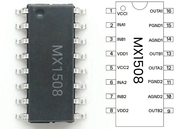
1) MX1508 IC Pinout?
You can see the pinout diagram of the MX1508 IC below.
2) MX1508 DataSheet?
As I already discussed in this article, there are equivalents and clones available, so we need to look after the exact IC located in our module. Anyhow, I am attaching two possible IC datasheets:
3) Maximum voltage of MX1508?
The maximum voltage of the MX1508, as per the official datasheet, is 9.6V. In case your module has TC1508 on it, then its maximum voltage will be 7.2V.
4) Can we use MX1508 to drive the stepper motor?
Yes, of course, you can use it to drive stepper motors. Make sure it is a bipolar stepper motor and does not exceed the voltage and current ratings of the MX1508.
5) Can we control speed using MX1508?
You can control the speed of a DC motor by supplying a PWM signal to the direction input pins of the module.
6) MX1508 vs L298N?
Generally speaking, the L298N is for higher power applications as it has a voltage range up to 46V and a current of 2A. With its heat sink version, the IC's temperature is easily maintained. On the other hand, the MX1508 is made for low-power applications like driving small motors, toy cars, etc. Depending upon the IC model, the voltage varies from 2 to 9.6V and the current varies from 0.8 to 2A.
Also, the controlling is a bit different when compared to each other. There is a dedicated PWM input pin for controlling speed in the L298N driver, but in the MX1508, the PWM signal can be provided to the direction control pins.
// Define pin connections and settings
const int ForwardPin = 6; // Pin for forward motor control
const int BackwardPin = 5; // Pin for backward motor control
const long ActionTime = 200; // Duration for motor action (milliseconds)
const int MaxSpeed = 110; // Maximum speed (0-255)
bool DirectionFlag = true; // Direction flag for motor control
void setup() {
// Set motor control pins as outputs
pinMode(ForwardPin, OUTPUT);
pinMode(BackwardPin, OUTPUT);
}
void loop() {
if (DirectionFlag) {
// Drive motor forward
analogWrite(ForwardPin, MaxSpeed); // Set forward motor pin to MaxSpeed
delay(ActionTime); // Wait for ActionTime
analogWrite(ForwardPin, 0); // Stop motor
DirectionFlag = !DirectionFlag; // Toggle direction flag
delay(20); // Short delay before changing direction
} else {
// Drive motor backward
analogWrite(BackwardPin, MaxSpeed); // Set backward motor pin to MaxSpeed
delay(ActionTime); // Wait for ActionTime
analogWrite(BackwardPin, 0); // Stop motor
DirectionFlag = !DirectionFlag; // Toggle direction flag
delay(20); // Short delay before changing direction
}
}

